Jacob Epshteyn

Jacob Epshteyn. Electrical Engineering with Computing at MIT, Class of 2029.

01 / 02 · MIT Hobby Shop · Oct 2025 – Apr 2026

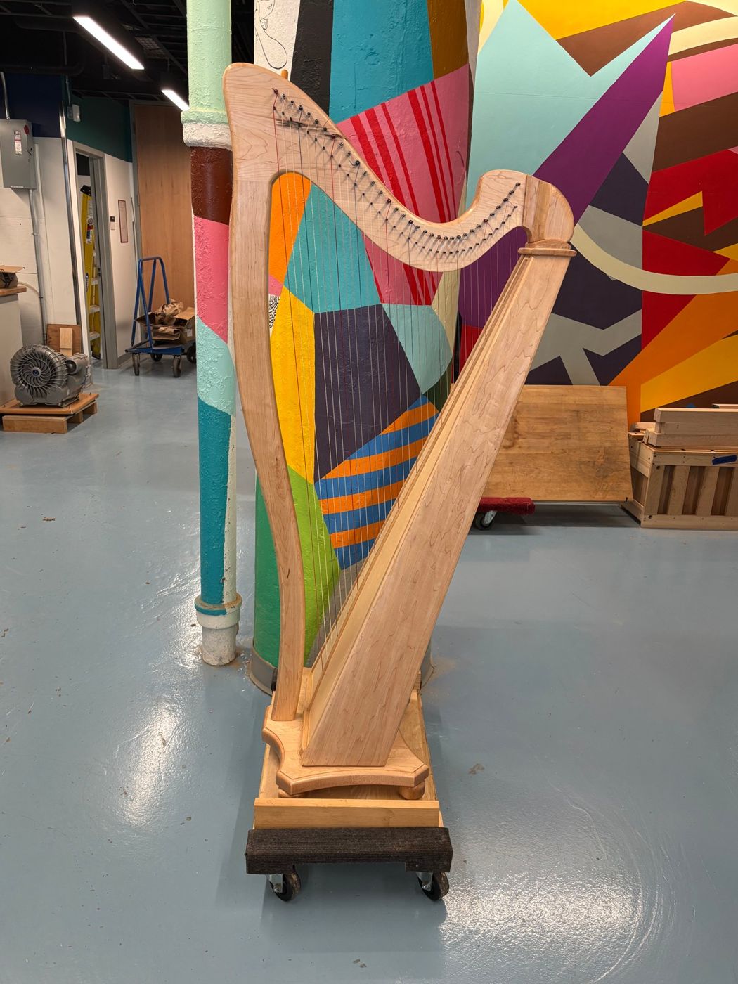
34-string lever harp

A five-foot instrument built through CNC machining, woodworking, precision drilling, hardware installation, and stringing. The project spanned two semesters and was my introduction to woodworking.

The design comes from MusicMakers, which provides it only as paper blueprints. I modeled the whole harp in Fusion 360 so its parts could be cut on a CNC router. Much gratitude is owed to the Hobby Shop staff, who provided endless support.

Strings
34
Height
About 5 ft
String tension
1,000+ lbs
CAD
Fusion 360, rebuilt from 2D paper blueprints
Fabrication
Jointing and planing, glue-ups, CNC routing, bandsaw, drill press, finishing, stringing
The finished 34-string lever harp, strung, on display at the Hobby Shop
Technical detail

How the harp was built

MusicMakers publishes this harp as paper blueprints written for hand tools: dimensions and angles for most parts, and traced outlines for the curves a builder would follow on a bandsaw. To cut the parts on a CNC router, I rebuilt every component in Fusion 360. Parts with dimensioned geometry I modeled straight from the drawings. For the freeform contours, especially along the neck, I imported scaled sections of the plans as reference images and redrew them with arcs, turning outlines meant to be cut by eye into exact profiles. I then put all the parts together in a digital assembly, which let me check that sizes, angles, and mating faces agreed before any wood was cut.

Before anything went on the CNC, the lumber had to be jointed and planed flat and square, and boards too narrow for a part were glued edge to edge into wider blanks. The router then cut the body, neck, pillar, soundboard, back, base, and structural strips from the model. Hardware holes came from the model too: the CNC located or started them, and I finished them on the drill press. Not everything suited the machine. The neck buildup, an irregular piece above the curved neck that gives it a symmetrical profile, I cut on the bandsaw with a jig.

The model describes a harp with no strings on it, and wood under more than 1,000 lbs of combined tension doesn't keep that shape. The plans leave the pillar's final length to be fitted during assembly, because the neck deflects once it's loaded, so I trimmed the pillar until the neck and pillar lined up. Stringing showed the same effect: as tension rose, the soundboard deflected enough to pull strings I had already tuned back out of tune, and it took several passes before the tuning settled.

The biggest problem came at full tension. The soundboard and its edge strips were glued to the soundbox, and during stringing that joint failed and the soundboard pulled away from the body. I re-glued it with a stronger adhesive and more careful clamping, and it failed again under tension. Since a better glue joint wasn't enough, I changed the joint itself: I added screws so that fasteners, not just adhesive, hold the soundboard against the pull of the strings, and hid the screw heads under wooden plugs. It hasn't separated since.

02 / 02 · Independent project · 2023 – 2025

Auralis

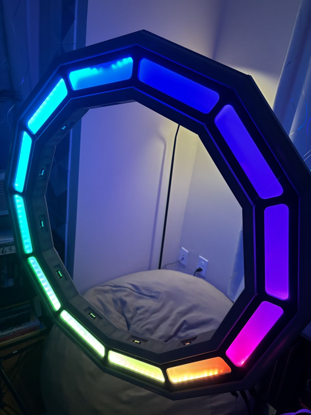
A hand-controlled electronic instrument. You play it by moving a hand over one of twelve note sensors set around an illuminated ring. It plays single notes and chords using several libraries of instrument sounds, and its programmable lights let it double as a light show.

I designed it over two summers and my junior year of high school, and learned CAD and programming along the way. It was inspired by Animusic, the animated series of automatic instruments. I performed it for my graduating class in 2025.

Sensors
12 × VL53L0X time-of-flight, two I²C buses of six
Controllers
Raspberry Pi Pico for sensors, Raspberry Pi 4B for sound, lights, and UI
Sound
FluidSynth with SoundFont instruments
Lighting
156 addressable LEDs, in 12 groups of 13
Enclosure
Modular illuminated frame, modeled in CAD
Auralis lit up, with each ring segment glowing a different color
Technical detail

How Auralis works

Each of the twelve notes is a VL53L0X time-of-flight sensor, which measures the distance to whatever is in front of it instead of waiting to be pressed. A note turns on when a hand comes within 20 cm of its sensor and stays on as long as the hand is there. Playing Auralis means reaching into and out of twelve invisible zones around the ring, one for each semitone of the octave, and holding several at once to play intervals and chords.

Wiring up twelve identical sensors was the main electronics problem. Every VL53L0X powers on at the same I²C address, so on a shared bus there's no way to tell them apart. I split the sensors across the two I²C buses of a Raspberry Pi Pico, six per bus, and gave each its own shutdown (XSHUT) line. At startup the Pico enables the sensors one at a time and assigns each a new address. From then on it only reads distances and streams them over serial to a Raspberry Pi 4B, where a background thread keeps a cache of the latest twelve readings. That way the music code reads from the cache rather than waiting on sensors.

The Pi 4B handles everything musical. It tracks which sensors are active, so a held hand sustains its note rather than retriggering it on every pass of the main loop, and pulling the hand away releases it. FluidSynth renders the notes from SoundFont instrument libraries, so the same twelve inputs can play different instruments without touching the hardware, and sounds that naturally decay are handled differently from sustained ones. A Kivy touchscreen panel sets the octave and instrument. It also has a chord mode, where one sensor plays a major or minor chord in a chosen inversion, or a chord that fits the selected key.

The same note state drives the lights. A group of thirteen LEDs sits behind each sensor, and animation code builds fades, held glows, and rotating gradients, lighting a chord's root brighter than its other notes. Each finished frame goes over Redis to a separate process that drives the strip, so the music code never deals with LED signal timing. Getting all of this to line up was as much a physical problem as a software one. The strip runs in a single line around a twelve-sided frame, so the code reverses and offsets the pixel order to match each light group to its sensor. I designed that frame in CAD to hold the sensors in consistent positions, carry the LEDs, and route the wiring, because the instrument only works if the twelve notes in software, the twelve light groups, and the twelve physical sensors agree.

Resume

One page covering education, technical projects, work experience, skills, and awards. PDF, updated October 2026.

Download resume